This tutorial will show you how to model a highly detailed basketball in 3ds Max using box modeling techniques. This tutorial is suitable for beginners but assume some basic knowledge. If you have zero 3ds Max modeling experience, try our Modeling a Chess Pawn tutorial first.
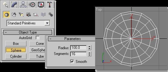
Step 1. Create a Sphere on the Top viewport with the following settings:
Step 2. Convert the Sphere to an Editable Poly:

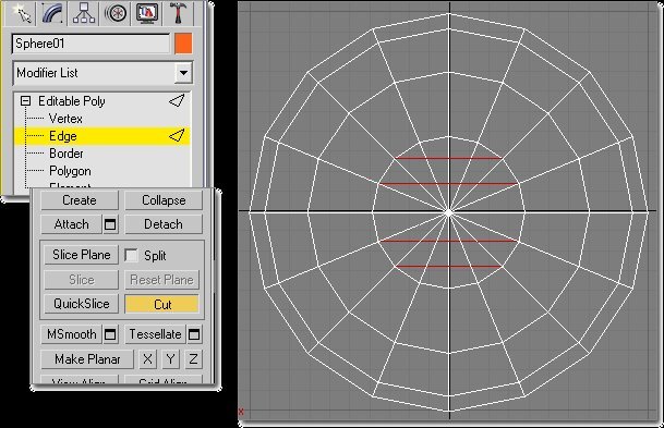
Step 3. Go to Edge sub-object level and cut the following edges:
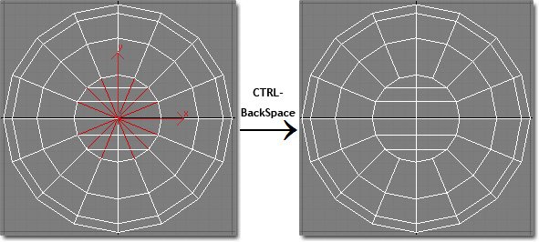
Step 4. Select the following edges, and press CTRL-Backspace to delete the edges (holding CTRL deletes the vertexes as well).
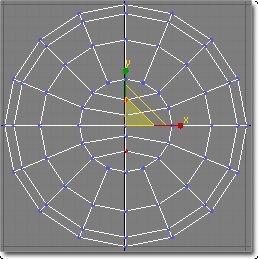
Step 5. Switch to Vertex sub-object level and select the vertexes as shown in the image below, and scale them down on the Y-axis to bring them closer together.

Step 6. Select the two vertexes as shown in the image below, and scale them up on the Y-axis to move them further apart.
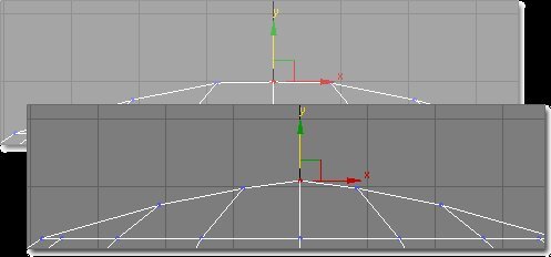
Step 7. Switch to the Left viewport and select the 4 vertexes as shown below, and move them upwards.
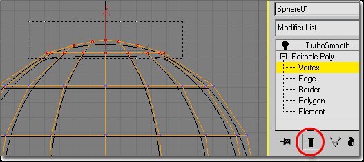
Step 8. Select the TurboSmooth or MeshSmooth modifier from the Modifier List and set the Iterations to 2.
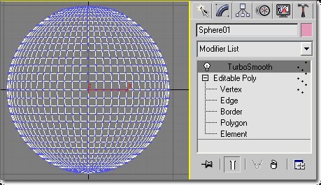
I enabled Isoline display for the TurboSmooth modifier, but that’s not required.
Step 9. Switch to Vertex sub-object level again and move the center top vertex up just a bit.
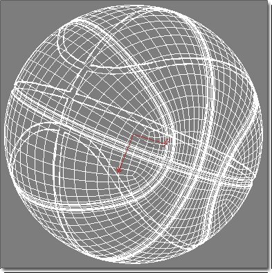
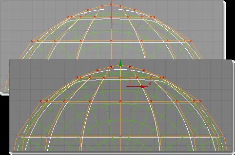
Step 10. Turn show end results on. This will allow you to see if the ball will become round in the next steps. Select the 21 vertexes as shown in the image below:
Step 11. Scale up vertexes selection on the Y-axis to move them further apart so the ball becomes round again.

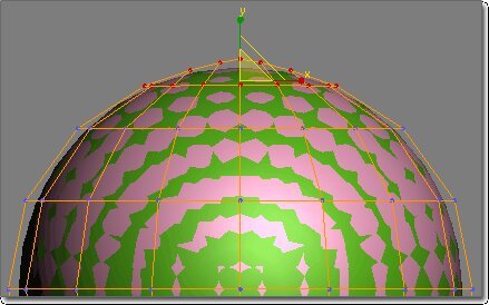
Step 12. The ball doesn’t need to be 100% smooth yet, it may have a small bump or indent as those will disappear later on when we add more details. But make sure the ball is at least round, and not egg-shaped for example. For the best results, you can add a second sphere, of the same size, but with 32 segments, on the same location, as a reference ball. You can skip this step and the following two steps if you can do this “manually”. Create the second sphere on the Left viewport starting from the center of the first sphere and you will see something like this:

Step 13. Press F3 to turn on shading in the viewport and your balls should look similar to the following image (the green ball is the second sphere we created as a reference):
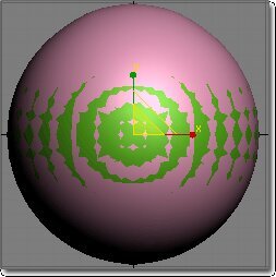
If you only see one ball, increase or decrease the size of the second sphere until they partly overlap. As you can see in the image above, we need to move down the top of the ball a bit to make it rounder, which we will do in the next step. Use F3 to turn on and off shading while performing these steps so you can see the results in a wireframe and shaded version.
Step 14. The goal is to make sure the balls overlap an almost equal amount on the top half of the ball. Select Sphere01 again, and press F3 to switch back to wireframe view. Go to vertex mode, select the 37 vertexes as shown in the image below, and move them down a bit.
Step 15. Select the 21 vertexes as shown in the image below, and move them down a bit, and then scale them up a bit. Toggle F3 to check the results. You should end up with something similar to the following:
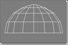
Step 16. When you are happy with the roundness of the top half of the ball select all the polygons of the bottom half of the ball and delete them. Also hide or delete the reference sphere.
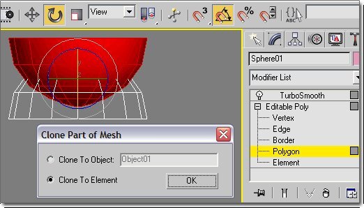
Step 17. Select all the other polygons. Press the Angle Snap Toggle button. Rotate the polygon selection 180 degrees over the X or the Z-axis while holding the Shift button. When you release the mouse button choose Element on the Clone Part of Mesh dialog box and press OK.
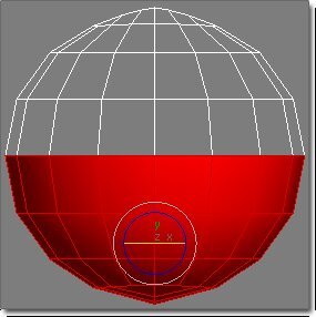
Step 18. Move down polygons to below the top half of the ball. Rotate (the bottom half) 90 degrees over Y-axis (horizontal).
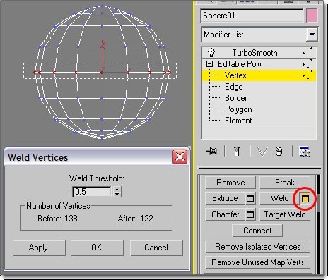
Step 19. Select the bottom row of vertexes of the top half and the top row of vertexes of the bottom half (see selection rectangle in image below), press the square button next to Weld. Increase the Weld Threshold as necessary until you have a total of 122 vertexes in the model. You should have 32 vertexes selected before welding, and 16 after welding.
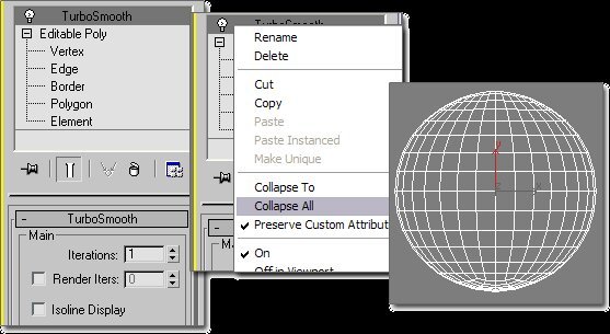
Step 20. Set the TurboSmooth or MeshSmooth modifier’s Iteration setting to 1. Right-click the modifier and select Collapse All.
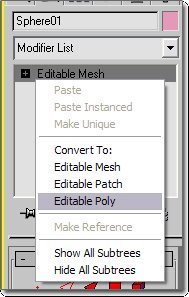
Step 21. The object turned into an Editable Mesh after collapsing the stack, so we need to convert it to an Editable Poly again. Right-click Editable Mesh and select Editable Poly below the Convert To option:
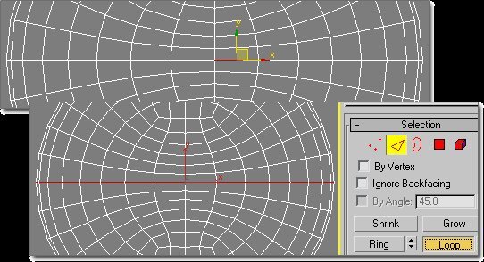
Step 22. Switch to the Top viewport, select the edge as shown below, and press the Loop button (or ALT-L).
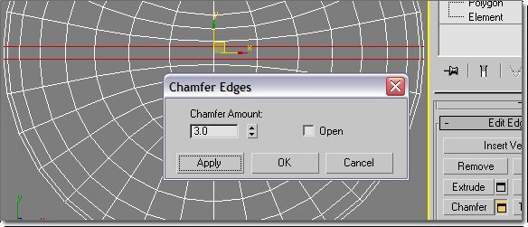
Step 23. Click the small square box next the to Chamfer button, and set the Chamfer Amount to 3, and press Apply.
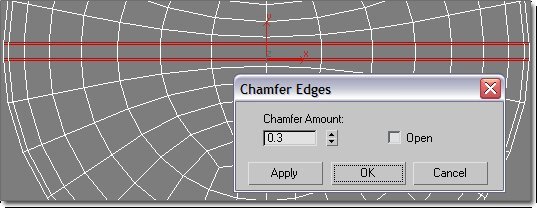
Then change the Chamfer Amount to 0.3 and press OK.
Step 24. Select the edge as shown below and press the Loop button (or ALT-L), and chamfer the edge loop in the same way you did in the previous step, first with Chamfer Amount 3, then with 0.3.
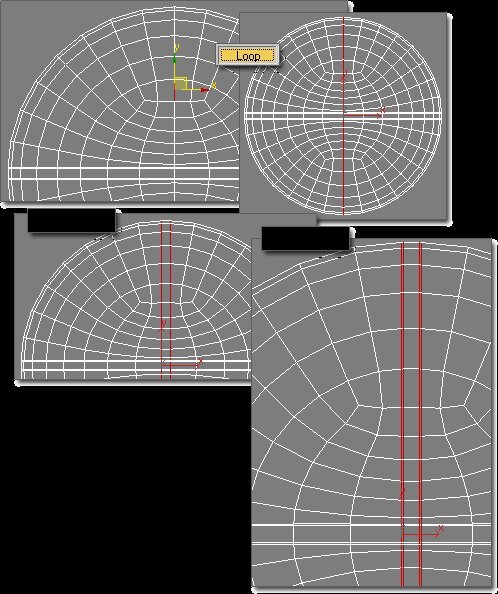
Step 25. Select the edge as shown below and press the Loop button (or ALT-L), and chamfer the edge loop in the same way you did in the previous step, first with Chamfer Amount 3, then with 0.3.

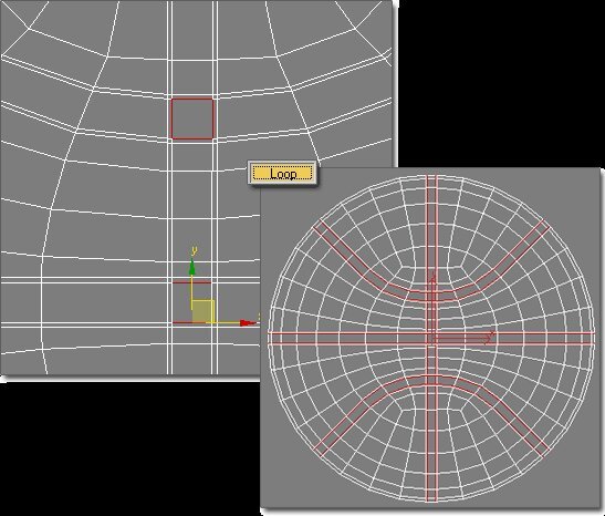
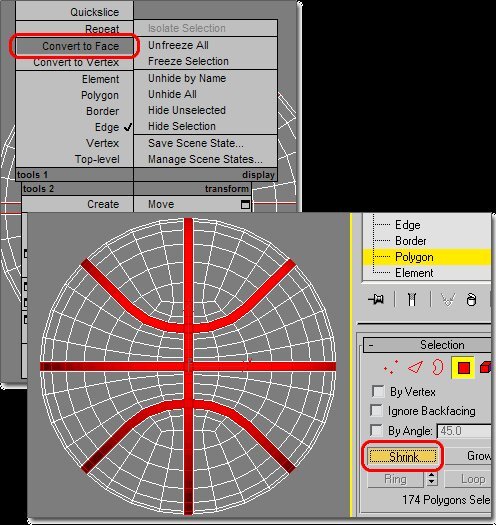
Step 26. Select the edges as shown below and press the Loop button (or ALT-L).
Step 27. Right-click on the viewport and select Convert to face. Press the Shrink button.
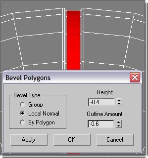
Step 28. Press the small square button next to the Bevel button. Enable the Local Normal option, set the Height value to -0.5, the Outline Amount to -0.1, and press Apply.

Step 29. Change the Height value to -0.4, the Outline value to 0.6, and press OK.
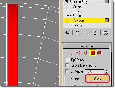
Step 30. Press the Grow button.
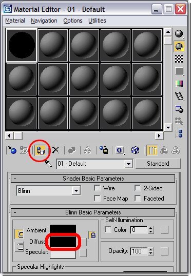
Step 31. Press the M key to open the Material Editor, change the Diffuse color of the first material to black, and assign it to the selected polygons.
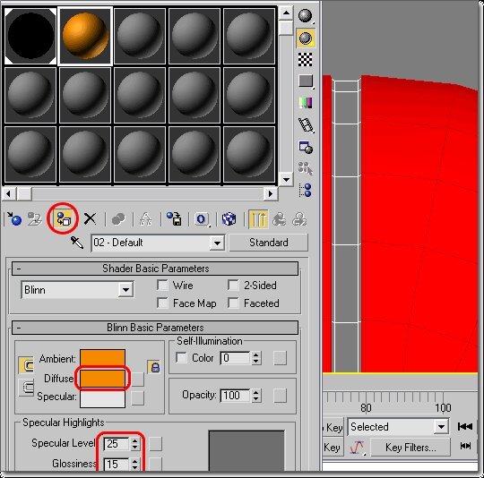
Step 32. Select Select Invert from the Edit menu (or press CTRL-i), and assign an orange material to the selected polygons. Set the Specular level to 25 and the Glossiness to 15.
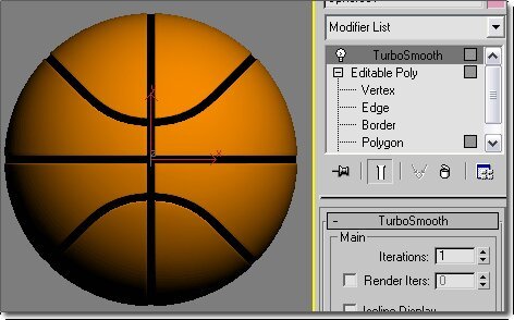
Step 33. Press F3 to turn on shading in the viewport. Assign a TurboSmooth or MeshSmooth modifier and set the Iterations to 1.
Step 34. Add a Noise map to the Bump slot of the orange material, and set the Size value in the Noise Parameters section to 1.0. And finally, render your basketball:
This tutorial is created originally for 3Dvalley.com. You are not allowed to redistribute this tutorial in any form.